As you will probably know, the legacy TTN v2 Stack will be shut down in December of this year, which means nodes on TTN v2 should be migrated to The Things Stack Community Edition (formerly known as TTN v3 Stack). Unfortunately, the TTS stack made it a little harder to run “incomplete” nodes like the AttNode v1 and v2, which in the default firmware don’t support downlink packets, and are therefore not exactly LoRaWAN Spec compatible.
Up until now the Lora Frame Counter, which is a security feature to prevent replay attacks, was reset every time the ATTiny rebooted (e.g. because of reset or power loss). Because of this the Frame Counter Check in the settings of the Lora devices had to be disabled, or messages after a reset wouldn’t be processed by the TTN Backend.
I have now implemented a way to save the Frame Counter in the ATTinys integrated EEPROM, so it will survive resets and power loss. Because of that the Frame Counter Check can now be left enabled when using the current Firmware (starting from git commit 361f8e0b85). Please be aware that the EEPROM is reset when flashing the ATTINY, therefore you will have to reset the frame counter in the TTN-Console when reflasing a device with enabled Frame Counter Checks.
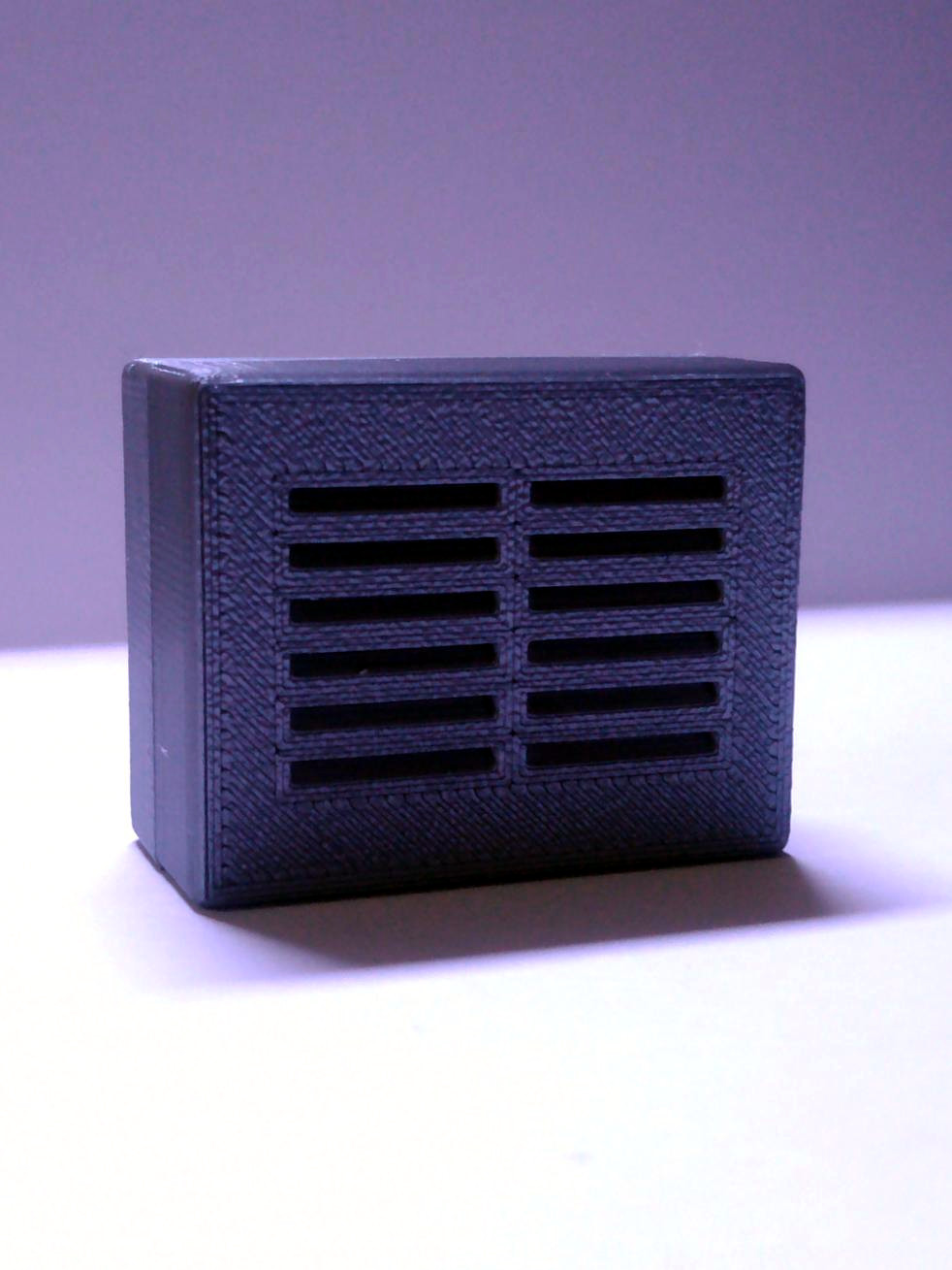
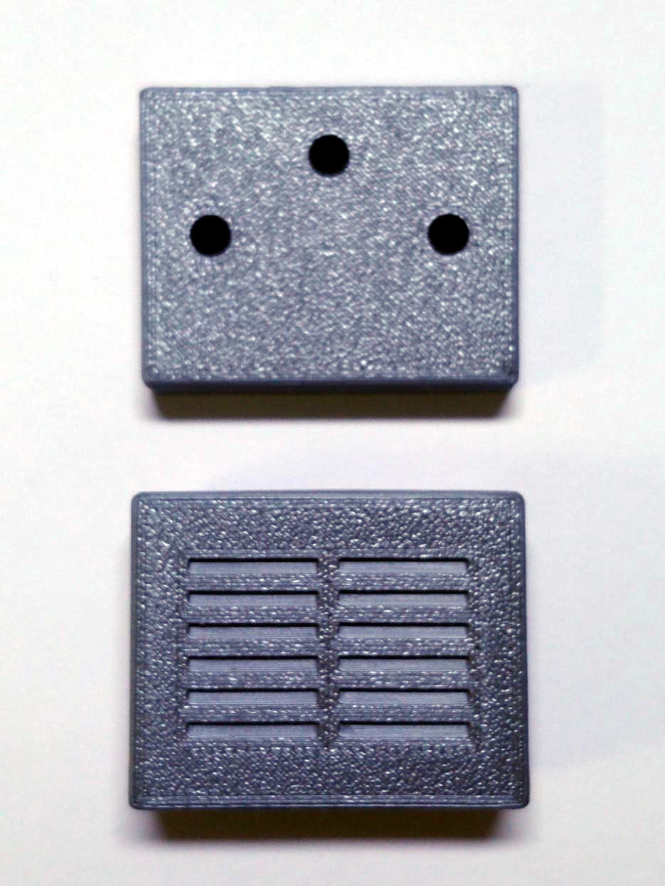
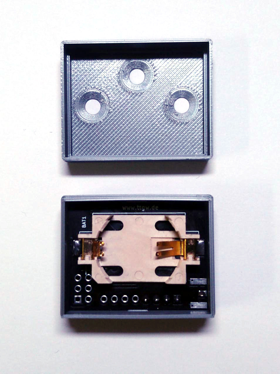
As promised I have now also designed a 3D-Printable case for the TinyLoRa v2 Boards. The Board is meant to be used with a small coil antenna directly mounted to the PCB. Here are some pictures:
My tests with the v2 prototype PCBs where successfull, I did not find any functional issues with the boards, and only some minor cosmetic issues.
Documentation of the TinyLoRa v2 PCB is now available on this site
. You can also find a ZIP with the Gerberfiles attached there, so you can order your own from the usual PCB prototyping companies.
After a long wait due to coronavirus outbreaks in China and resulting delays in the PCB production it is finally here, The first prototype of the TinyLoRa v2 Board:
The triple use footprint for u.fl, SMA and wire antenna seems to work as intended, and the rest of the board works as before. So all in all a sucessfull first prototype run.
Some more development on the TinyLoRa v2 board. I have modified the SMA connector footprint in such way, that it should now be possible to also use a U.FL Connector or use a Wire- or Coil Antenna instead of the SMA edgemount connector. With this change it should be possible to use all of the most common types of antennas with the node. I also did some more cleanup and finishing touches:
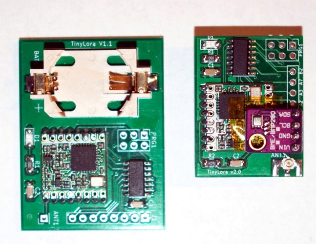
Here is a sneak peek at the next iteration of the TinyLoRa PCBs. I got it down to roughly half the size compared to the v1 board by making it a two sided board and putting the battery holder, which is by far the biggest component, onto the Backside. I also added the possibility to use a edge-mounted SMA connector for the antenna.
Because of the battery at the back the sensors don’t fit there anymore, so the GPIO-connector was flipped by 180° so the sensor now mounts over the front of the board. There are still some finishing touches to be done before I will put them into production, but it shouldn’t be to much work. As I don’t have any real boards yet here are some renders from KiCAD: