Since the TinyLoRa Node does seem to get some interest in the last days the question of power consumption and deep sleep currents came up a few times. So here are some measurements I took as well as a way to potentially more than halve the deep sleep current when using one of the usual BME280 sensor modules.
Deep Sleep Current Measurements
I use the ATTiny84s deep sleep / powerdown feature and the internal watchdog to keep the power consumption low and get a useful battery life with a CR2032. To get an idea how good/bad this works I did some measurements. i
| Test Arrangement | Deep Sleep Current |
|---|---|
| TinyLoRa without a Sensor | ~ 4.4µA |
| TinyLoRa with BME280 Module (Stock) | ~ 10.7µA |
| TinyLoRa with BME280 Module (modified) | ~ 4.5µA |
So some interesting observation here, just adding a stock BME280 module as found on e.g ebay more then doubles the deep sleep current. If we look into the datasheet of the sensor, the sleep current of a BME280 should be around 0.1µA. So where does this extra consumption come from?
Modifying the BME280 Module for Low Power Use
A typical Arduino compatible BME280 module from the usual sources has to be usable at 5V, as this is the typical voltage used by many of the arduinos and clones. The BME280 itself is a 3.3V part, the maximum rating for the input voltage is 3.6V, so hooking it up to an arduino directly would probably kill it. To avoid this the typical modules have an onboard 5V to 3.3V regulator. This is typicaly a small 3 pin part. On my modules it is on the backside, I have marked it on this picture:
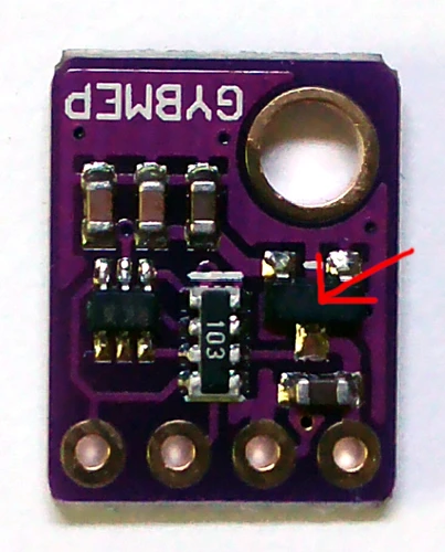
These voltage regulators have a small quiescent current, which is not that relevant if used in a normal arduino or Raspberry Pi use case, but in this very low power situation it is quite significant. Here it’s adding about 6.2µA to the deep sleep current of the node, which more than doubles its power usage when idle. Since the node is already running at a save voltage for the BME280 (the CR2032 is nominal 3V and a fresh one rarely reaches 3.3V) we don’t need the regulator at all, and can just power the sensor directly. To achieve this, the regulator needs to be desoldered from the module and the power input and power output pad need to be bridged together. To find out which pins have to be bridged, use a multimeter in continuitiy test mode. There should be one pad connected to the VIN pin, one conneted to the GND pin, and one connected to the rest of the circuit and the sensor. We need to bridge the pad connected to VIN with the one connected to the sensor. Be careful not to bridge any of the two other pads to the one connected to GND, as this will result in a short circuit. Here is a picture of a moded sensor (excuse the crude soldering job, this was just a quick hack to test if it works ;) ), I used a left over leg from a trough hole resistor as bridge “wire”:
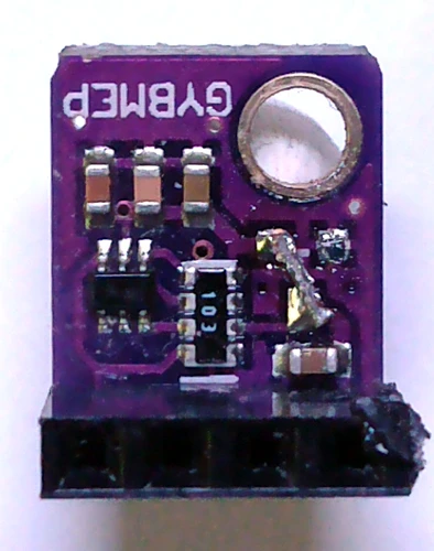
Please beware that there are quite a few different BME280 modules out there. Make sure you know what you are doing before attempting this. After successfully modding the sensor, the deep sleep current should now be at around 4.5µA. This should give a good boost in battery runtime, since the node is sleeping most of the time. I don’t have any runtime values yet for a modded node, but since nodes with unmodded sensors have worked for several months on a single CR2032 already, it will take a while to get any long term data.
I think the same mod should also be possible with the SHT21 sensors, which the firmware also supports, since at least the modules I use look more or less the same. I will test this as well after checking the datasheet for the values to expect.