The ATTNode (short for ATTiny Node) is a minimalistic node for the LoraWAN Network. It is based on the widely available ATTiny MCU from Atmel/Microchip and the HopeRF RFM95W LoRa Wireless Module. It can be used with a variety of sensors, the provided firmware does support the I²C-sensors SHT21 and BME280 for measuring climate data (Temperature/Humidity/Atmospheric Pressure) and is meant to be used with The Things Network
as backend. The node can last for several months using only a CR2032 button cell sending values from the above mentioned sensors every 10 minutes.
Features
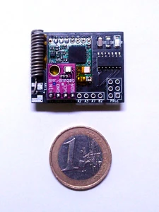
Small Size, only 47x36mm (v1) / 34x26mm (v2) / 37.5x30.5 (v3)
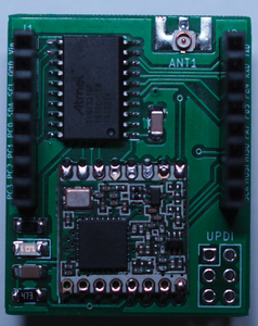
Based on widely available Atmel ATTiny84(v1,v2) / ATTiny3216(v3) MCU and RFM95W LoRa-module
Free GPIO-Pins from the ATTiny + Power to connect sensors on a 2.54mm pitch header
Firmware support for SHT21/BME280 Climate Sensors, Brightness Measurement, Alarm Trigger and Beacon Mode
Optional on-board LED for status signaling
Powered by a single CR2032 lithium battery
Long battery runtime using the ATTinys deep sleep mode
Integrated 6-Pin programming header
Small component count
Possibility for edge-mount SMA connector or u.fl SMD connector (v2/v3)
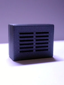
Open Hardware and Software, KiCad Project for the PCB, Firmware and Case Designs can be found in the git repository
Downloads for Gerber- and STL-files as well as the BoM and assembly hints can be found at the subsites for the corresponding ATTNode Version.
My tests with the v2 prototype PCBs where successfull, I did not find any functional issues with the boards, and only some minor cosmetic issues.
Documentation of the TinyLoRa v2 PCB is now available on this site
. You can also find a ZIP with the Gerberfiles attached there, so you can order your own from the usual PCB prototyping companies.
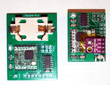
After a long wait due to coronavirus outbreaks in China and resulting delays in the PCB production it is finally here, The first prototype of the TinyLoRa v2 Board:
The triple use footprint for u.fl, SMA and wire antenna seems to work as intended, and the rest of the board works as before. So all in all a sucessfull first prototype run.
Some more development on the TinyLoRa v2 board. I have modified the SMA connector footprint in such way, that it should now be possible to also use a U.FL Connector or use a Wire- or Coil Antenna instead of the SMA edgemount connector. With this change it should be possible to use all of the most common types of antennas with the node. I also did some more cleanup and finishing touches:
Here is a sneak peek at the next iteration of the TinyLoRa PCBs. I got it down to roughly half the size compared to the v1 board by making it a two sided board and putting the battery holder, which is by far the biggest component, onto the Backside. I also added the possibility to use a edge-mounted SMA connector for the antenna.
Because of the battery at the back the sensors don’t fit there anymore, so the GPIO-connector was flipped by 180° so the sensor now mounts over the front of the board. There are still some finishing touches to be done before I will put them into production, but it shouldn’t be to much work. As I don’t have any real boards yet here are some renders from KiCAD: