Overview
Firmware for the ATTNode v3 is developed using PlatformIO , which can be used with the Atom Editor or Visual Studio Code on all major platforms. The code of the reference firmware can be found in my git repository . The firmware code uses PlatformIOs Arduino Framework for the Atmel MegaAVR Platform.
The firmware uses the OTAA method to activate the device instead of ABP which was used by the v1/v2 nodes. Deep Sleep is supported, as well as the SHT21 and BME280 sensor. It’s also possible to change the sending interval at runtime via LoRa Downlink.
Compile Time Configuration
Before using the firmware you have to copy the file in src/config.example.h to src/config.h. Before compiling and uploading to the board there are some configurations to do in config.h Most options are described with comments in the config.example.h, but will also described here (at times there might be options in the firmware that are not yet added to this documentation)
#define LED_PIN PIN_A7
Sets the pin where the Signaling LED is connected. in the default PCB Layout LED D1 is connected to the ATTiny at Pin A7. If set, the LED will blink twice to signal a successfull OTAA join (which can take severals seconds from powerup).
#define WS2812B_PIN PIN_PC1
#define WS2812B_NUM 2
#define WS2812B_BRIGHT 32
This will enable support for the WS2812B RGB LEDs on the CO2 addon board. Currently this is only usefull with installed CO2-Sensor addon, leave this disabled otherwise.
#define BTN_PIN PIN_PC2
When enabled, connecting PIN_PC2 of the node to GND will immediately take a measurement and send it. For the MH-Z19C Addon board, Holding the button for more than 4 seconds will also trigger a calibration to 400 ppm (Make sure the sensor was outside for at least 20 Minutes before doing this).
#define NUM_SENSORS 1
This setting controls the number of enabled sensors. Please make sure it is always set to the correct number of sensors enabled from the section above. So for example to enable the MH-Z19C CO2 Sensor and BME280 it should look like this:
#define NUM_SENSORS 2
#define HAS_BME280
#define HAS_MHZ19C
Not all sensors can be used at the same time. For example only one sensor using the serial UART can be used at once. Also you can’t use multiple BME280 or SHT21 at the same time. Keep in mind that RAM and Flash are limited. Using to many sensors at once may lead to firmware crashes or flashing failures.
#define HAS_NO_SENSOR
#define HAS_MHZ19C
#define HAS_SG112A
#define HAS_SENSAIRS8
#define HAS_SCD30
#define HAS_BME280
#define HAS_SHT21
#define HAS_HM330x
#define HAS_DS18B20
Sets which sensors are connected to the node. This will include the needed code for the choosen sensor as well as setup the payload format accordingly. Choosing HAS_NO_SENSOR will just send the battery voltage (e.g. for testing nodes without a sensor) all other enabled sensors will be ignored in this case.
Some sensors might have configuration options, like used pins or sensor resolution. See the Sensor Configuration section in config.example.h for the details
uint16_t sleep_time = 10;
This sets the time to sleep between measurements / sending. The actual sleep time will be sleep_time x 64 seconds. The default 10 from the example therefore means 640 seconds of sleep between measurements. This will not be an exact value between received data, as airtime and the send queue in the LMIC can add some seconds of delay as well. This value can be overwritten at runtime via LoRa Downlink. As soon as a value is set via downlink it will take precedence over the value set here.
static const u1_t PROGMEM APPEUI[8]={ 0x00, 0x00, 0x00, 0x00, 0x00, 0x00, 0x00, 0x00 };
static const u1_t PROGMEM DEVEUI[8]={ 0x00, 0x00, 0x00, 0x00, 0x00, 0x00, 0x00, 0x00 };
static const u1_t PROGMEM APPKEY[16] = { 0x00, 0x00, 0x00, 0x00, 0x00, 0x00, 0x00, 0x00, 0x00, 0x00, 0x00, 0x00, 0x00, 0x00, 0x00, 0x00 };
This sets up the needed keys for OTAA activation. The keys can be obtained from the TTN Console if you use TTN. if you use ChirpStack instead be aware that APPEUI is always set to all 0x00 there and you will only need to set DEVEUI and APPKEY.
Attention: APPEUI and DEVEUI have to be in LSB order, which is the opposite of what is displayed by default in the TTN-Console. The byte order can be switched in the console to copy the keys in the right order. The APPKEY is in the correct order (MSB) by default.
LoRaWAN-Bandplan and other LMIC settings are set as build_flags in the platformio.ini. Please see the documentation of the LMIC Library
for details
Programming
The ATTNode v3 uses UPDI for programming by default in contrast to the SPI programming used on the ATTNode v1/v2. This means you will need an UPDI-capable programmer. The programming header is using the pinout defined by the MicroUPDI Project and includes UPDI Programming as well as serial debugging and power. The PlatformIO Project is pre-configured to use the MicroUPDI-Programmer. If you want to use another option like pyupdi consult the PlatformIO Documentation on how to configure this.
Attention: If you program a node for the first time or changed the board config in platformio.ini you’ll have to use the Set Fuses option in PlatformIO once to set the needed fuses on the ATTiny. After this the normal Upload function is sufficient for all code or config.h changes.
Debugging
The firmware has the ability to produce some debug output via the Serial UART as long as there is no sensor using the UART. The settings for the serial port are 115200 Baud 8n1 by default.
To enable it, uncomment the line -D DEBUG in platformio.ini. This will produce some debug output showing the state of the node. The following macros are available as a replacement for the normal Serial.print and Serial.println functions:
DEBUG_PRINT("Debug Output");
DEBUG_PRINTLN("Debug Output with Linebreak");
These will only produce additional code in the firmware when the DEBUG-Flag is enabled, and will be entirely removed in the ouput binary if not. The macros work like the normal Serial.print* statements form the standard arduino functions.
Runtime Configuration
It is possible to change the sleep time / sending interval via LoRa Downlink packets. This makes it possible to remote-configure nodes without reflashing them.
To set a sending interval it has to be scheduled as a downlink paket for the node as a 2-Byte uint value. To set an interval of 10 minutes for example, one has to send the value 0x000A (10 as a 2-Byte Hex), for 5 minutes it would be 0x0005 and so on. If you want to reset the node to the compiled in value just send 0xFFFF. Here is an example setting the interval to 10 at the TTN-Console:
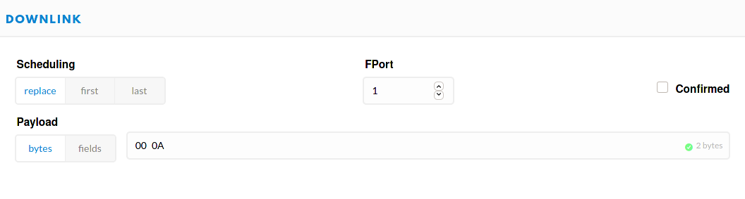
Please be aware that the actual sleep time is not exactly the set value in minutes, but rather the set value times 64 seconds. So a value of 10 would mean 640 seconds for example. Cause for this is that the ATTiny3216 sleeps for 32s at a time, so a value of 10 means it sleeps 20 times for 32 seconds.
The received value will be stored in the internal EEPROM of the ATTin3216, so the node will restore the last configured interval after a reset / power loss.
Payload Decoder
Due to the very variable nature of possible sensors with the AttNode v3 Firmware, it is necessary to use a decoder matching the configured sensors of a device. You can generate the matching decoder for your choosen sensors with the Payload-Decoder Generator . The generator page is also included in the git-repo at payload/index.html for local use