Overview
This is the second redesign of the ATTNode PCB. The size of the v3 is at 37.5x30.5mm. Main difference to the previous versions is the usage of the new ATTiny 3216 MCU. This Chip is quite a bit more powerfull and also has more IO-cabapilities compared to the ATTiny84 used before. The more potent MCU makes it in theory possible to use the full LoRaWAN LMIC (including Downlink, which is not possible on the v1/v2 due to memory/flash size constraints) and also now has HW-Support for Serial UART and I2C among other improvements. The ATTNode v3 is not meant as a replacement for the v2, but an alternative version for applications where the v2 with its ATTiny84 is not enough.
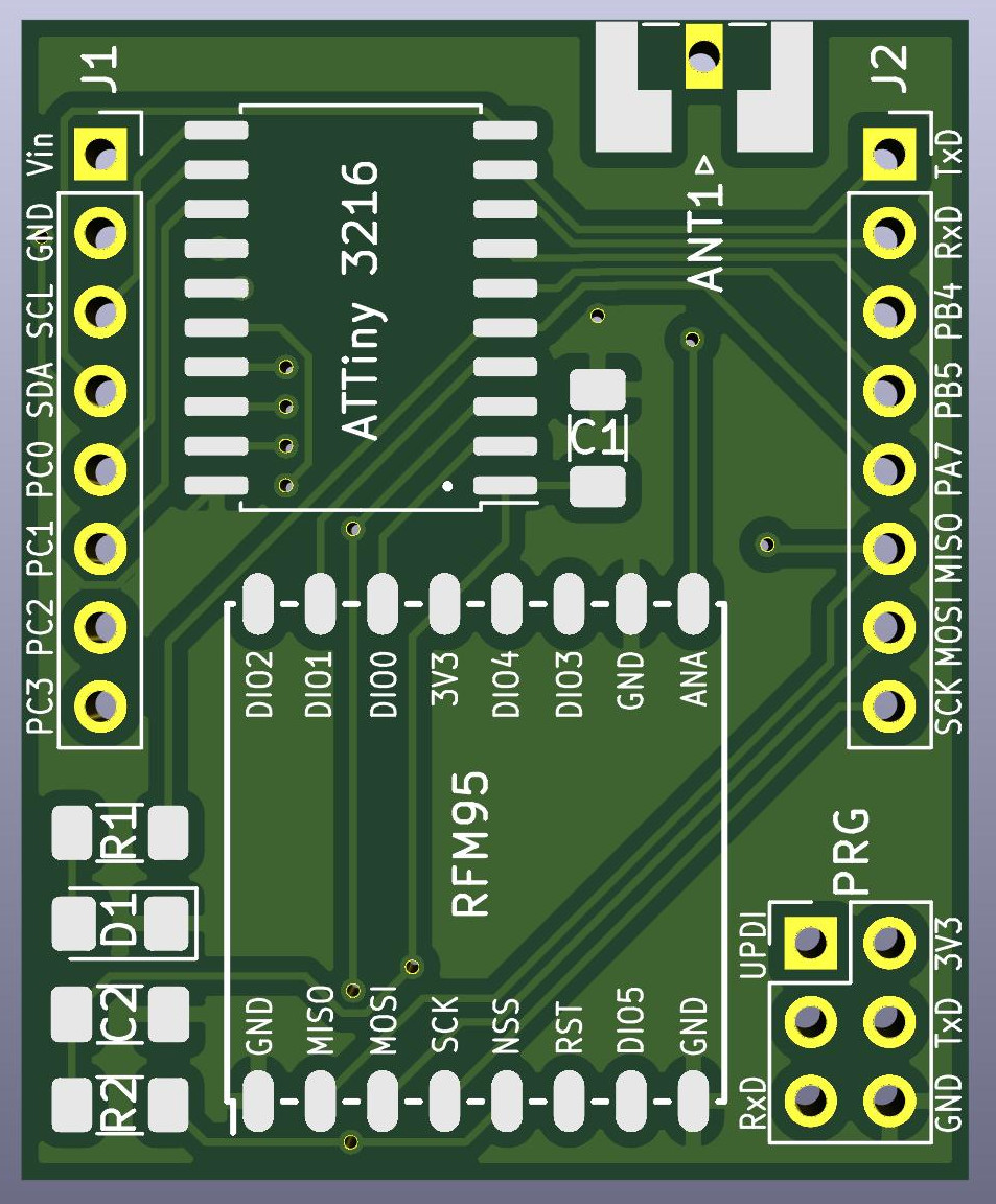
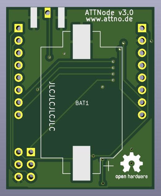
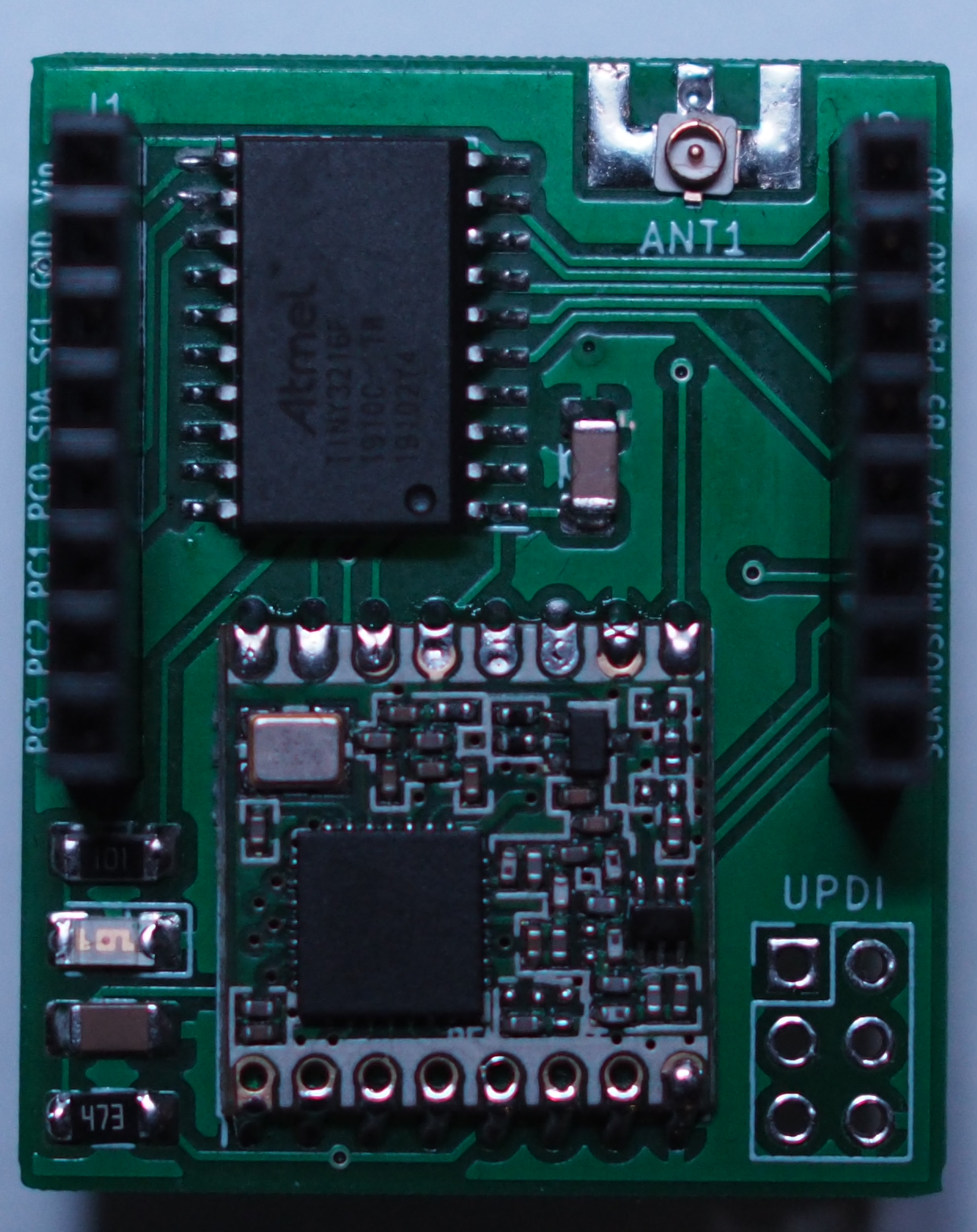
Here are some renders of the final PCB and one of my Prototype Boards:
Parts List / BOM
| PCB Marking | Part | Notes |
|---|---|---|
| D1 | LED SMD 1206 | |
| R1 | Resistor 100Ω SMD 1206 | Only if LED is used, choose the value fitting for the selected LED |
| R2 | Resistor 47kΩ SMD 1206 | |
| C1,C2 | Capacitor 100nF SMD 1206 | |
| ATTiny3216 | ATTiny3216 | SOIC-20 Package |
| RFM95 | HopeRF RFM95W Module | |
| BAT1 | CR2032 Battery Holder | |
| ANT1 | SMA Edge-Mount or u.fl Connector | It's also possible to use a simple wire- or coil antenna instead of a connector. |
| GPIO Pins | Exposes the IO-Pins of the ATTiny 3216 |
Supplier Links
Here are some links to my usual suppliers for the parts mentioned in the BOM above:
- List at Reichelt Elektronik SMD passives, battery clip, ATTiny 3216
- RFM95W at Aliexpress directly from China, because expensive and hard to get locally
Sensors are usually sourced from Ebay. I buy them from this supplier , which always worked out nicely so far.
There might be cheaper sources for all of the above mentioned components, this list is only for convenience. I’m not affiliated with the suppliers above in any way. If any of the links stops working, feel free to give me a hint, I don’t check them for changes regularly.
Assembly Hints
My preferred order of soldering the components is:
- ATTiny3216 (Pin 1 is marked with a white Dot on the PCB - align the marking on the ATTiny with the Dot)
- LED, Resistors, Capacitors (LED polarity matters, the cathode has to point towards the RFM95W)
- RFM95W (pads are marked on the PCB, align accordingly)
- Antenna Connector (if used)
- Battery Holder (backside)
- Sensor Module Mounted on Standard 2.54mm-Pitch Headerpins
- Wire-/Coil Antenna (if no Antenna Connector is used)
A general hint for soldering SMD parts: Use enough flux (I personally use a flux pen with liquid flux, but the type doesn’t matter as much). It really helps to prevent solder bridges especially between the ATTiny84 Pins and helps to achieve better/prettier solder joints in general.
Programming and Firmware
The firmware for the ATTNode v3 can be found in this Git Repository . It does support the basic functionality (Deepsleep, LoRa OTAA Activation, Setting Send Interval via Downlink, BME280 and SHT21 Sensors) and is usable as a starting point for implementing support for other sensors. Right now it does not have all the functionality and documentation of the v1/v2 firmware.
Cases
There are two known Case Variants available at the moment:
- My original design (see Downloads below), which is mainly meant for ATTNodes with a directly attached BME280 / SHT21 and a coincell battery
- The modular case desing from itsybitsy here on Thingiverse which can accomodate addon boards and has modular parts for additional sensors and a AAA battery case
Downloads
- Gerber Files (for PCB Production): attnode-gerber-v3.0.zip
- 3D-Printable Case
- Front Part: attnode-v3-front.stl
- Back Part (with mounting holes): attnode-v3-back-holes.stl
- Back Part (without mounting holes): attnode-v3-back-noholes.stl
- Case Design (OpenSCAD): attnode-case-v3.0.scad