Overview
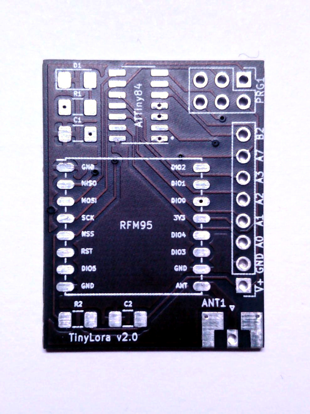
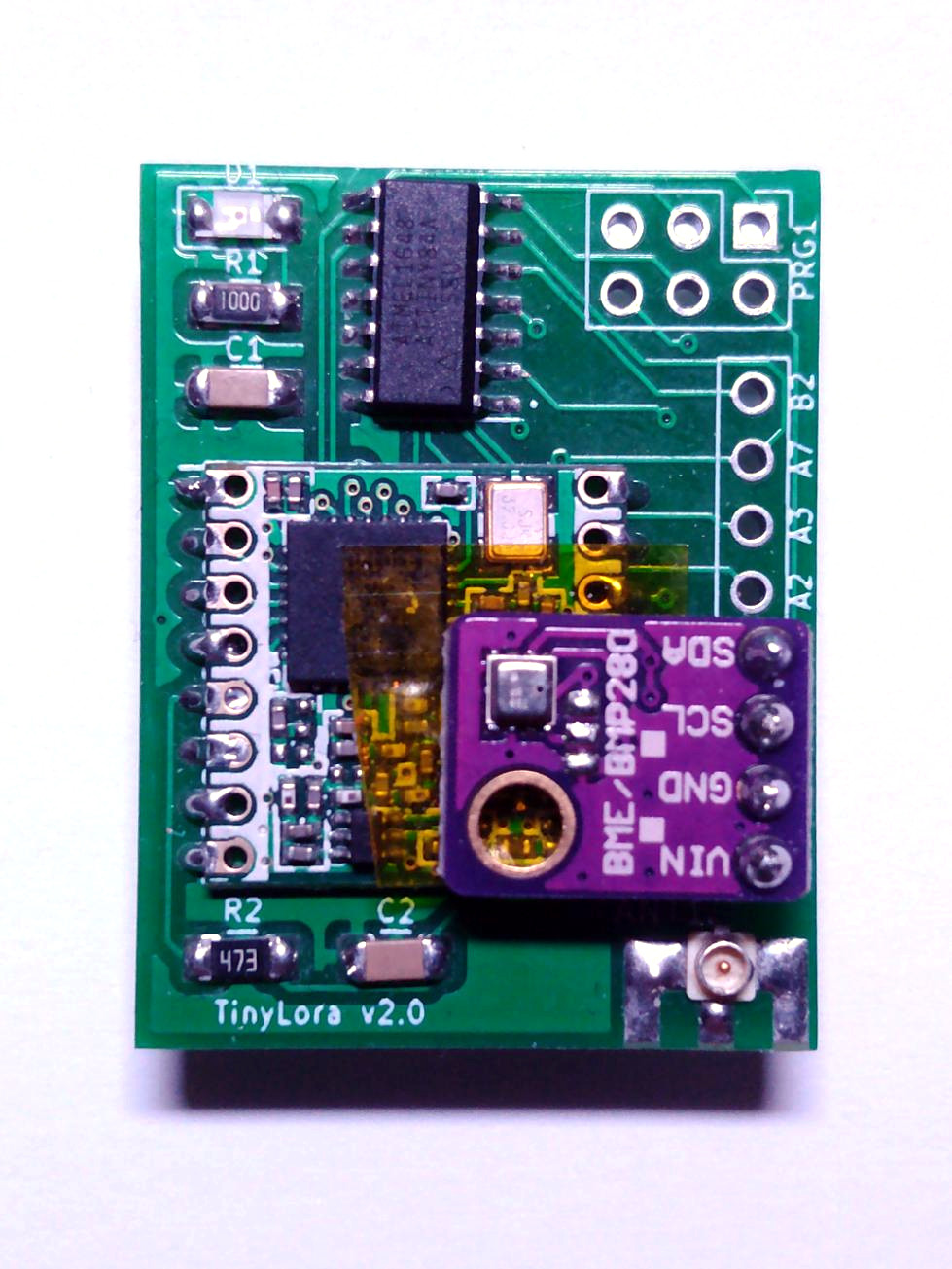
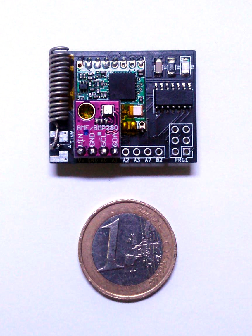
This is the first redesign of the ATTNode PCB. The size is now only 34x26mm, so roughly half the size of the v1 Boards. I also incorporated a triple use antenna mount, which can accomodate an u.fl or SMA connector as well as a wire-/coil antenna as before. Here are some pictures of the v2 prototypes:

Parts List / BOM
| PCB Marking | Part | Notes |
|---|---|---|
| D1 | LED SMD 1206 | |
| R1 | Resistor 100Ω SMD 1206 | Only if LED is used, choose the value fitting for the selected LED |
| R2 | Resistor 47kΩ SMD 1206 | |
| C1,C2 | Capacitor 100nF SMD 1206 | |
| ATTiny84 | ATTiny84A-SSU | SOIC-14 Package |
| RFM95 | HopeRF RFM95W Module | |
| BAT1 | CR2032 Battery Holder | |
| ANT1 | SMA Edge-Mount or u.fl Connector | It's also possible to use a simple wire- or coil antenna instead of a connector. |
| GPIO Pins | SHT21 / BME280 Module (with default firmware) | Make sure the modules pinout matches with the PCB pinout. Default firmware uses A0 as I²C SCL and A1 as I²C SDA. |
Supplier Links
If you don’t want to search for the matching parts yourself here are some links to my usual suppliers. Please note that there might be cheaper options available at the time of your buying, so you might pay more than necessary if you use these links. Also I’m not afilliated with the linked suppliers in any way. If links don’t work anymore feel free to give me a hint (I don’t check them regularly)
Here is a link to german electronics supplier Reichelt which has most of the SMD components in stock:
I usually get the RFM95 directly from China via AliExpress:
Instead of the SMA connector listed in the Reichelt BOM above it is also possible to use an u.fl connector:
The sensors are the normal I²C breakout modules as found on Ebay / Aliexpress. Please make sure the pinout matches with the ATTNode PCBs.
Assembly Hints
My preferred order of soldering the components is:
- ATTiny84 (pin 1 is marked with a white dot on the PCB - align the marking on the ATTiny with the dot)
- LED, Resistors, Capacitors (LED polarity matters, the cathode has to point to the PCB edge)
- RFM95W (pads are marked on the PCB, align accordingly)
- Antenna Connector (if used)
- Battery Holder (backside)
- Sensor Module Mounted on Standard 2.54mm-Pitch Headerpins
- Wire-/Coil Antenna (if no Antenna Connector is used) - If you want to use the 3D-Printable Case, make sure to mount the coil antenna on the front side of the board (where the RFM95 module is) along the short board edge. Make sure the antenna doesn’t short out the capacitor/resistor underneath. A simple method to avoid this is to put the antenna in some heatshrink tubing.
Please Note: If your used sensor module has exposed contacts or components at the underside (like the BME280 module I used), it is advised to put some insulating tape between the module and the RFM95 to avoid unwanted short circuits.
A general hint for soldering SMD parts: Use enough flux (I personally use a flux pen with liquid flux, but the type doesn’t matter as much). It really helps to prevent solder bridges especially between the ATTiny84 Pins and helps to achieve better/prettier solder joints in general.
Programming
A detailed guide for configuring the firmware and programming it to the node can be found at the Firmware Page
Downloads
- Gerber Files (for PCB Production): attnode-gerber-v2.0.zip
- 3D-Printable Case (STL)
- Front Part: attnode-v2-front.stl
- Front Part with Hole for 3mm LED: attnode-v2-front-led.stl
- Back Part with Mounting Holes: attnode-v2-back-holes.stl
- Back Part without Mounting Holes: attnode-v2-back-noholes.stl
- Case Design (OpenSCAD): attnode-case-v2.0.scad